by Craig DiLouie, LC, CLCP and C. Webster Marsh, CLCP, Lighting Controls Academy
This article is based on an updated course, EE102A: Occupancy and Vacancy Sensors, at NEMA Academy. To take a quiz and get course credit, click here.
INTRODUCTION
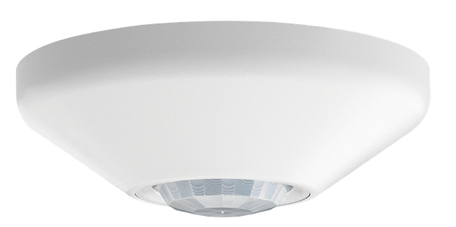
Occupancy (aka, occupant) sensors monitor spaces to determine whether they are occupied or vacant, producing a control signal that can be used to automatically switch or dim lighting. By ensuring lighting operates only when it is needed, occupancy sensors produce energy cost savings in addition to benefits such as convenience and enhanced security. According to the Open Access journal Sensors, occupancy-based lighting controls can reduce lighting energy consumption in commercial buildings by up to 45% (Chaudhari et al., 2024).

Image courtesy of Acuity Brands
Because these devices are relatively simple to install, cost-effective, and widely required by energy codes, occupancy sensing is a staple in new construction projects, renovations, and many lighting upgrades.
OCCUPANCY SENSOR TECHNOLOGY
An occupancy sensor’s performance depends on the technology it is using and how that technology is configured for the application environment. While it may seem like all sensors are the same, a wide range of sensor types is available. Key considerations when selecting a sensor include:
• Occupancy sensor functionality
• Sensitivity and coverage pattern
• Sensing technology
• Switching and dimming
• Communication method
• Mounting method
• Power source
• Special features
• Accessories
OCCUPANCY SENSOR FUNCTIONALITY
Occupancy sensors may be specified as:
• Automatic Full-On
• Automatic Partial-On
• Manual-On (vacancy mode)
These categories pertain to the sensor’s behavior.
Automatic Full-On controls automatically turn lighting On to full output when occupancy is detected.
Automatic Partial-On controls automatically turn lighting On to a reduced level (commonly 50%) when occupancy is detected and allow the occupant to raise the lighting level from a user interface device (e.g., wall keypad).
Manual-On (also called Vacancy mode or Vacancy sensor) controls require the occupant to manually turn the lighting On using a user interface device (e.g., a wall-mounted button).
In all circumstances, the sensor will automatically adjust the lighting to its Off state or a reduced level after a predetermined period following the last occupancy detection.
Prevailing commercial building energy codes require lighting to be operated in Manual-On or Partial-On mode in the majority of space types. Manual-On and Partial-On strategies typically save more energy because occupants may choose to leave lighting Off or at a lower level. Full-On strategies prioritize convenience and may be considered for spaces where providing a user interface would be difficult or where safety or security requires it.
While simple On/Off control is common, to save energy, strategies that operate lighting at different output levels based on occupancy are often ideal for spaces where lighting must remain On for safety/security reasons but are infrequently occupied, such as a corridor or warehouse aisle.
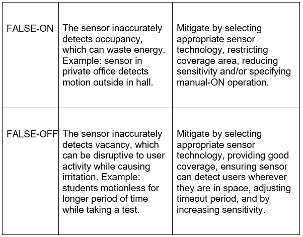
Nuisance switching (false On / Off) occurs when lighting turns On or Off unintentionally due to incorrect sensor detection, often caused by improper sensor placement, excessive sensitivity, or environmental factors such as air movement, heat sources, or vibration. Nuisance switching may be categorized as false-On or false-Off.
SENSITIVITY AND COVERAGE PATTERN
An occupancy sensor’s ability to detect motion depends on its sensitivity, which determines detection distance for:
• major motion (e.g., walking)
• minor motion (e.g., hand movement, typing)
Coverage is commonly described by:
• coverage area: the boundaries within which the sensor can detect motion
• coverage pattern: the shape of the detection field (circle, rectangle, ellipse, teardrop, etc.)
NEMA WD-7 provides standardized testing and reporting methods for occupancy sensor coverage performance. Published coverage specifications are typically provided as a maximum for major motion and may be affected by:
• Sensitivity settings
• Room dimensions
• Mounting height
• Obstacles and partitions
• Surface reflectivity
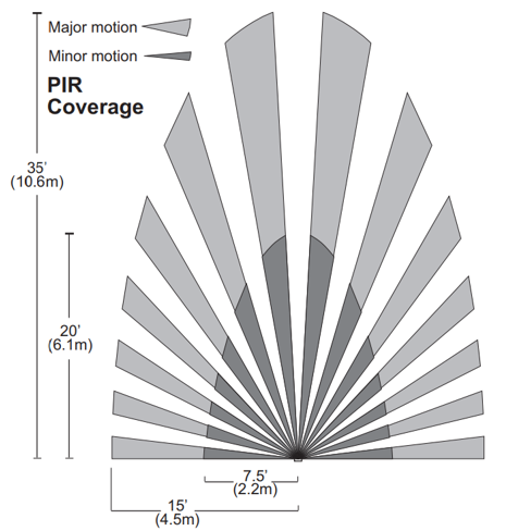
Image courtesy of Legrand
OCCUPANCY SENSING TECHNOLOGY
The most common sensing methods include:
• Passive infrared (PIR) sensors detect motion by sensing changes in infrared energy (heat) emitted by an object relative to the background environment.
• Ultrasonic (US) sensors actively emit a high-frequency ultrasonic signal into the space and detect motion by analyzing changes in the reflected signal (frequency shift and/or amplitude).
• Acoustic sensors detect occupancy by using a microphone to identify sound patterns associated with human activity, filtering background noise to recognize changes caused only by occupants. This technology is often used in combination with other technologies to increase detection reliability.
• Microwave sensors detect occupancy by emitting low-power microwave signals and analyzing changes in the reflected signal caused by movement within the coverage area.
• Dual-technology sensors combine two sensing methods to improve reliability and reduce nuisance switching, such as PIR/US or PIR/acoustic.
In addition, emerging approaches are being explored, including camera-based and light-differential sensing.
PASSIVE INFRARED
A PIR sensor works by comparing infrared (IR) readings between two distinct sensing elements within the sensor. When idle, both sensing elements detect equal IR radiation from the environment; when a warm body passes, it triggers a “differential change” in IR levels between the elements, causing the sensor to detect motion. PIR sensors require a line of sight; they cannot “see” occupants behind obstacles or glass.
The detection mechanism is a multi-faceted lens that defines the coverage area as a series of discrete fan-shaped zones, each containing a sensing element. The lens determines the type of motion (major or minor) the sensor is best suited to detect over a given floor area. See the example below for a wall-mounted sensor, recommended for a maximum major motion coverage of a 32-ft. x 32-ft. area, and maximum minor motion coverage of a 22-ft. by 24-ft. area.
The sensor detects motion as described above when an occupant crosses the detection zones (making it more sensitive to motion occurring lateral to the sensor). The gaps between the zones widen with distance from the sensor, which results in a decrease in sensitivity as the distance from the sensor increases. Most PIR sensors can detect major motion (walking movement) up to about 40 ft. but are sensitive to smaller minor motion (hand movement) up to about 15 ft.
Since power consumption is relatively low, PIR sensing technology is commonly used in battery-powered occupancy sensors.
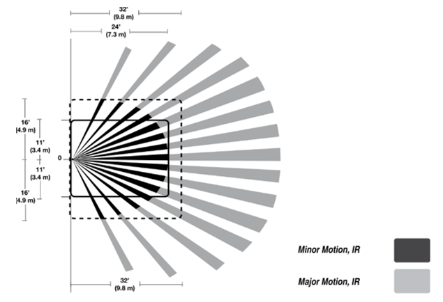
Image courtesy of Cooper Lighting Solutions
ULTRASONIC
US sensors emit an ultrasonic high-frequency signal throughout a space, monitor the frequency of the reflected signal, interpreting a change in frequency as motion. Alternately, US sensors can set up a standing wave and look for changes in both amplitude and frequency due to interaction with a moving object. To avoid incompatibilities with devices such as hearing aids, the frequency of the emitted waves (typically 32-40 kHz) is well above what the normal ear can detect (20 kHz).
Since coverage is volumetric, US sensors do not require a direct line of sight, making them well-suited to applications such as public restrooms with multiple stalls.
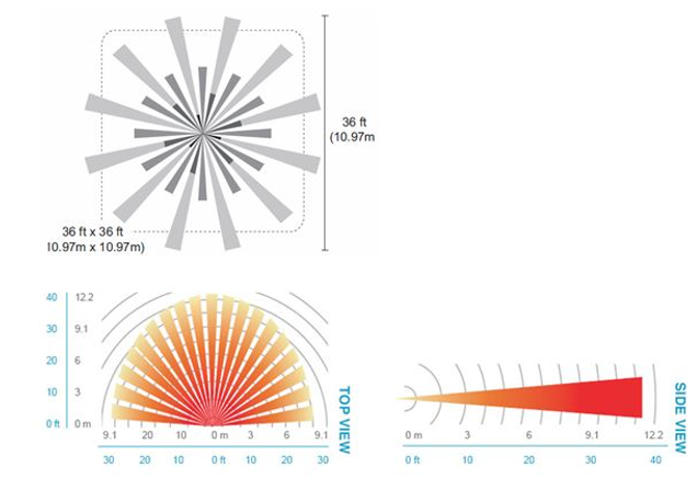
US sensors are able to detect minor motion at a distance up to 25 ft., making them highly sensitive. The coverage pattern for a 360-degree coverage showing both major motion and minor motion detection area is shown below.
US sensing technology is “always On” and typically requires a consistent connection to electrical power.
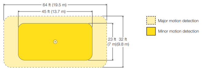
Image courtesy of Lutron Electronics
ACOUSTIC
Acoustic sensing detects occupancy by listening for sound patterns associated with human activity. Using an integrated microphone, the sensor analyzes variations in sound levels and frequency to determine whether a space is occupied. Advanced signal processing filters out steady background noise and focuses on short-duration sounds such as typing, paper movement, chair movement, or conversation.
Because acoustic sensing does not rely on motion or line-of-sight detection, it can be effective in spaces where occupants remain relatively still for long periods of time. For example, a person working quietly at a desk may produce small sounds that maintain the lighting On even when motion is minimal.
To ensure reliable performance, acoustic sensors must be calibrated to distinguish between meaningful occupant activity and ambient background noise. Acoustic sensing is typically combined with PIR sensing in a dual-tech sensor to maximize detection reliability.
Since power consumption is relatively low, acoustic sensing combined with PIR sensing is well-suited to battery-powered occupancy sensors.
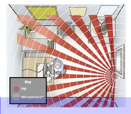
Image courtesy of Acuity Brands
MICROWAVE
Microwave sensors work similarly to US sensors in that they emit low-power microwave signals into a space, monitor the reflected signal frequency, and interpret changes as motion.
Microwave sensors do not require a direct line of sight. The emitted signal can pass through some materials such as glass, plastic, and lightweight partitions, allowing the sensor to detect movement behind obstacles.
Microwave sensors provide highly sensitive detection in relatively large areas. Because the emitted waves reflect off surfaces throughout the space, coverage is volumetric and can detect both major and minor motion.
However, the ability of microwave signals to penetrate certain materials means that sensors may detect motion outside the intended control area if not properly located or configured. For this reason, careful placement and sensitivity adjustment are important to avoid nuisance switching.
Microwave sensing technology is “always On” and typically requires a consistent connection to electrical power.
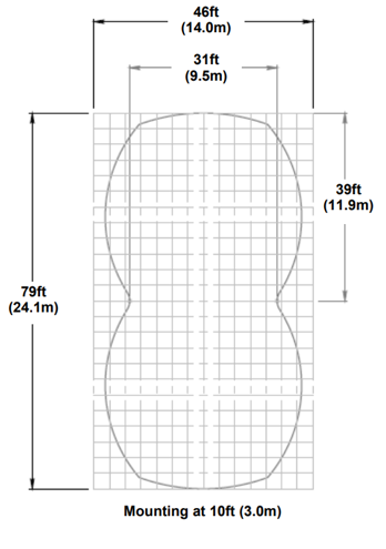
Image courtesy of mwConnect
DUAL TECHNOLOGY
Dual-technology (DT) sensors combine two sensing methods to improve detection reliability in applications where accurate detection is critical. They are often used in spaces where occupants may remain relatively still for extended periods (such as classrooms, conference rooms, and private offices), where single-technology sensors may be more prone to false-Off events. Dual-technology sensors are also used in environments where false-On events can occur due to adjacent motion, activity, or disturbance, potentially triggering the sensor to turn the lighting On.
Most dual-technology sensors combine PIR with either US or acoustic sensing. By using two detection methods, these sensors can better distinguish between actual occupancy and environmental disturbances.
A key consideration when specifying dual-technology sensors is how the sensor initiates detection and how it maintains occupancy status. These functions are sometimes described as the primary and secondary detection methods, respectively.
In PIR-Only Initiation mode, the sensor uses PIR as the primary detection method while the space is vacant. Because PIR requires line-of-sight motion, this approach helps prevent false-On switching caused by environmental noise or minor disturbances. Once PIR detects movement and the lights turn On, the sensor may use either or both technologies to monitor the space for occupancy.
In Dual Detection Initiation mode, both sensing technologies must detect occupancy before the lights turn On. This approach further reduces the likelihood of false-On events but may slightly delay activation compared to PIR-only initiation.
In Bi-Detection Initiation mode, either sensing technology detects occupancy before the lights turn On. This approach increases the sensitivity of detection and decreases the delay between when an occupant enters a space and the lights turn On, but it also has a higher potential for false-On events.
COMMON CONFIGURATIONS OF DUAL-TECH SENSORS
Dual-technology sensors can significantly improve detection reliability when properly selected and installed, particularly in spaces with limited motion, partitions, or other conditions that challenge single-technology sensors.
PIR + US (Active Dual Technology)
In this configuration, PIR and US detect entry into the space and maintain the lights On by detecting minor motion such as typing or small body movements, combining the advantages of the PIR line of sight sensing with the volumetric sensing provided by US sensing. The sensors can be reconfigured to utilize any of the initiation methods listed in the previous section. These sensors are called active dual-tech sensors because they continuously emit ultrasonic wave energy into the space and typically require a constant power source to support their active sensing.
PIR + Acoustic (Passive Dual Technology)
Another dual-technology configuration combines PIR with acoustic sensing. These sensors are often called passive dual-technology sensors because they do not emit energy into the space. Instead, the acoustic component uses a microphone to detect sound patterns associated with occupant activity while filtering out steady background noise. Because these sensors do not require a constant power source, they can be battery-powered or self-powered.
Images courtesy of Legrand and Acuity Brands
COMMUNICATION METHOD
Occupancy sensors that do not directly interact with lighting (via an integrated relay) communicate with lighting control devices to turn lighting On, turn lighting Off, or adjust lighting levels. The communication method determines how occupancy signals to luminaires, power packs, relays, and other lighting control devices are transmitted. Depending on the system architecture and application, sensors may communicate using contact closure, low-voltage control wiring, or digital network communication.
Contact Closure Switching sensors communicate using a contact-closure output. The sensor opens or closes a dry contact to signal another control device (such as a relay, power pack, or lighting controller) that occupancy has been detected. Contact-closure communication allows sensors to control multiple lighting circuits or integrate with non-lighting systems.
Low-Voltage Communication sensors send occupancy status via low-voltage wiring, using a simple analog communication method. A single sensor may control multiple lighting circuits, or multiple sensors may control a single load, providing implementation flexibility. Low-voltage sensors are commonly used in larger spaces, such as open offices and classrooms.
In Networked Lighting Control (NLC) systems, sensors communicate digitally with luminaires or control devices through a wired or wireless network communication protocol. These systems allow occupancy data to be shared across multiple devices or systems, enabling more advanced control strategies. Networked communication provides greater flexibility because devices, systems, and even luminaires can often be reconfigured through software rather than rewiring.
TIME DELAY
Time delay is the period between the last detected motion and when the lighting turns Off or reduces output.
Energy codes and standards commonly limit the time delay to a maximum of 20 minutes, though some older codes may allow 30 minutes, and some newer codes and standards require a maximum of 15 minutes.
Benefits of shorter time delays:
• increased energy savings
Drawbacks of shorter time delays:
• increased risk of false-Off
• may require more sensors or an improved layout and increased sensitivity settings
Note that unlike fluorescent light sources, there is no detrimental effect to LED source life from more frequent On-Off switching due to shorter time delay settings.
In NLC systems that enable programmable sequences of operation using conditional logic, the time delay may be programmed to vary by time of day or to work conditionally with time clock operations.
For example:
• occupied hours: 20-minute time delay
• after-hours: 5-minute time delay
MOUNTING METHODS
Sensors may be configured for ceiling, high wall/corner, wall switch (wallbox), workstation or luminaire mounting.
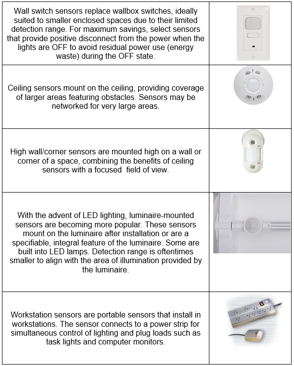
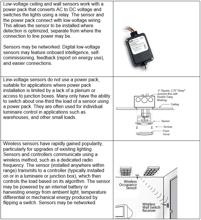
POWER SOURCES
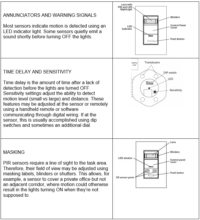
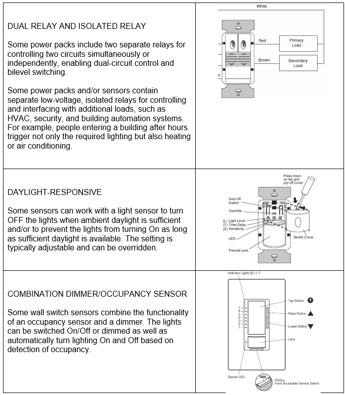
SPECIAL FEATURES
ACCESSORIES
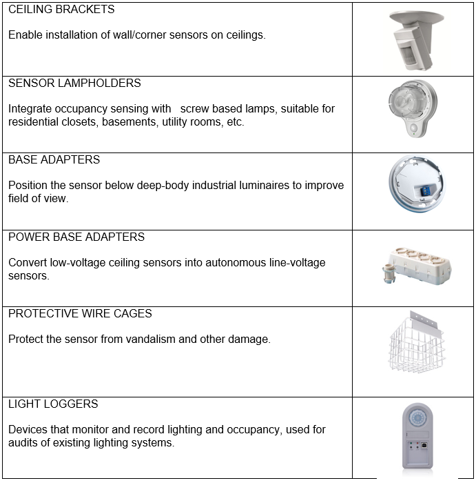
OCCUPANCY SENSOR APPLICATION
 Occupancy and vacancy sensors are ideally suited for installation in:
• smaller, enclosed spaces.
• larger spaces using zoned/networked or individual luminaire control.
• spaces that operate on an unpredictable schedule.
• spaces that are intermittently occupied—that is, left unoccupied for two or more hours per day; and
• stairwells, corridors, and similar spaces where the lighting must remain On all day but are frequently unoccupied, where lighting does not need to be Full On at all times (due to safety requirements).
Space types that are suitable for occupancy installation include offices, classrooms, copy rooms, restrooms, storage areas, conference rooms, warehouse aisles, break rooms, corridors, filing areas, and other spaces.
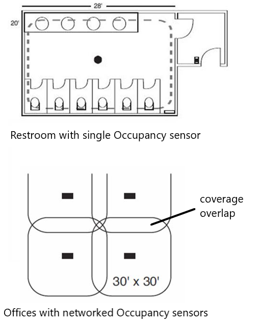
OCCUPANCY SENSOR APPLICATION (EXAMPLES)
Two examples are shown below: a public restroom (top) with a single sensor and an open office (bottom) with multiple networked sensors.
In the restroom, a ceiling DT sensor is placed about 2 ft. beyond the stall door to provide adequate coverage of the space.
In the open office, multiple ceiling US sensors are wired in parallel and networked to cover the entire space as a single load. Only one sensor is required to turn the lights On and keep them On. Note the minimum 20% overlap in coverage area recommended to ensure reliability of detection.
Images courtesy of Legrand Wattstopper
ENERGY CODES
 Most commercial building energy codes require lighting be turned Off or reduced when not in use. These codes apply to new construction and renovation projects and, in some states, certain lighting upgrades as well.
The majority of codes now specifically require sensors in a wide range of spaces.
See our Energy Codes courses for more information.
APPLYING PIR SENSORS
PIR sensors can be installed on ceilings or walls, including as a wall switch replacement, and used in both indoor and outdoor applications. They are well-suited to:
• smaller, enclosed spaces such as private offices, utility closets, and storage rooms;
• spaces requiring limited coverage, such as warehouse aisles and corridors; and
• relatively confined outdoor spaces, such as building perimeter lighting.
See the example below for the detection pattern of a PIR sensor in a small closet.
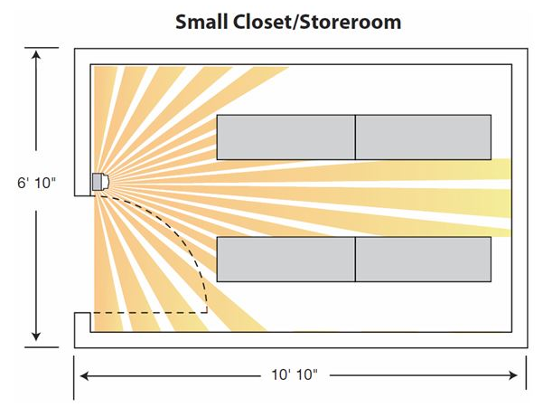
Image courtesy of Hubbell
PIR sensors should be located so that they have an unobstructed (line-of-sight) view of the primary task area. (Note that areas where detection is not desired can be masked at the factory by design or in the field through adjustment). If the lighting is full- or partially On, they should turn the lights On immediately when an occupant enters the room.
PIR sensor detection sensitivity decreases with increasing distance from the occupant to the sensor. They are most sensitive to motion lateral to the sensor. The sensor’s coverage area should be confirmed to ensure it monitors only the lighting in the designated space.
To prevent false-On switching, PIR sensors should not be mounted within 6-8 ft. of HVAC air diffusers or other heat sources.
See the example below for the detection patterns of PIR sensors monitoring warehouse aisles.
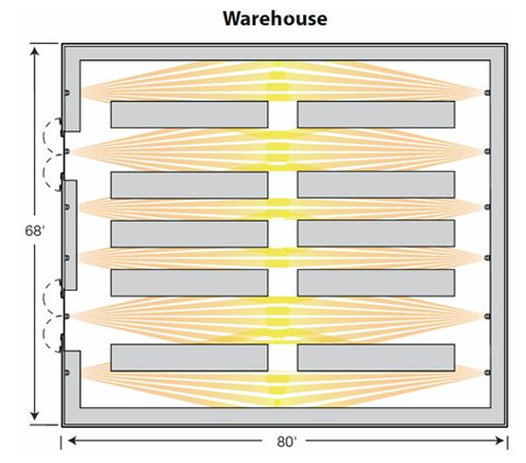
Image courtesy of HubbelL
APPLYING US SENSORS
US sensors emit high-frequency sound waves into the space and detect occupancy by measuring changes in the frequency of the reflected sound waves. They may produce a standing wave and measure both frequency shift and amplitude.
They can be installed on ceilings or walls, including as a wall switch replacement, typically in indoor applications. Although they are continuously emitting energy into the space, properly designed devices will not interfere with local devices such as hearing aids. They are well-suited to applications requiring greater sensitivity and reliability, open indoor spaces, and spaces with obstacles.
Suitable applications include open offices, private offices, bathrooms, classrooms, and conference rooms.
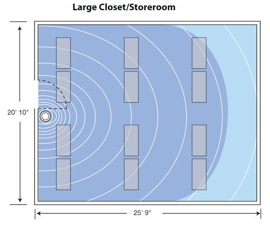
Image courtesy of Hubbell
US sensors do not require a line of sight to the primary task area. They can “see” around corners and obstacles, and have volumetric coverage—that is, they monitor the entire space and do not rely on the field of view. Unlike PIR sensors, US sensors’ field of view cannot be masked, but their detection area can be increased or decreased through sensitivity setting adjustments.
US sensors should be located so that the lights turn On as soon as an occupant enters the space. They are more sensitive than PIR sensors to occupants walking directly towards and away from the sensor and are ideal for applications with minor body motion, such as typing in an office or test-taking in a classroom.
US sensor sensitivity may be limited by three factors: distance, partition height, and the ability of room surfaces to reflect the ultrasonic emission. They operate best in spaces with ceilings below 14 ft. Room surfaces such as heavy carpeting, sound-absorbing partitions, or ceiling tiles may reduce sensor sensitivity, whereas hard surfaces may increase it. Additionally, the ceiling-mounted sensor’s effective range declines proportionally to partition height.
Because the US detection range can be reduced by both fabric partitions and high partition heights, it may be helpful to add PIR detection, add more sensors, or increase the sensor’s sensitivity.
To avoid false-On switching, US sensors should not be mounted on sources of vibration or within 6-8 ft. or air sources such as open windows and ventilation apertures.
See the example below for the detection range of a US sensor in a large restroom.
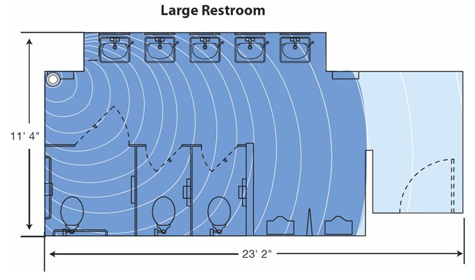
Image courtesy of Hubbell
APPLYING DUAL-TECHNOLOGY SENSORS
Dual-technology sensors can be more effective at preventing false-Off switching than PIR sensors and preventing false-On switching than US sensors for spaces where line of sight is blocked by obstructions or where occupants are relatively still for long periods of time. Because of this, DT sensors will generally perform better than single-technology sensors.
See the example below for detection patterns of dual-technology sensors in a large classroom.
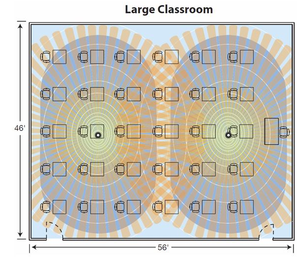
Image courtesy of Hubbell
Image courtesy of Wattstopper
Improper occupancy sensor mounting location is a leading cause of application problems, making sensor location a critical design decision. Sensors should be located so they reliably detect occupancy (or vacancy) with minimal nuisance (false-On or false-Off) switching. Typically, sensors are placed above or close to the main areas of activity in the space.
Another aspect of location is orientation. For example, the receiving side of a US sensor should be positioned toward the area of greatest traffic in a space.
Manufacturers may provide application support including project layout and sensor location services.